Duct Balloon®
Inflatable Isolation Barriers -

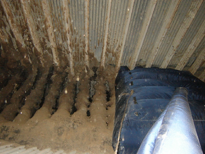
In this application, this customer was looking for a way to temporarily seal off the bottom slope of a large coal fired boiler at the start of a short outage. The work scope entailed sand blasting numerous locations inside the boiler to remove heavy slag deposits from the walls of the tubes. But before sand blasting could take place, the lower slope of the boiler needed to be protected by installing wood planking beneath the 60º sloped tubes shown in the picture below. Before installation of the planking, the potential existed for existing debris to come down into the work area where the planking installation contractor was working. The total area that needed to be temporarily sealed off was 10’ (3.04m) wide x 58’ (17.67m). Another requirement was that the gaps between the existing wall tubes opposite the access doors also needed to be sealed to prevent any debris from bypassing the inflatable barrier. Entry into the work area was accomplished by any one of the six existing access doors that were spaced about 10’ ( 3.04m) apart and measured 21” x 15” (533mm x 381mm)
In order to be able to pass this size Duct Balloon through one of access doors it was supplied in two sections. The first section was inserted through one of the access doors, partially inflated, and then guided into position using rope tied to the D rings. The second section was then inserted through an adjacent access door, partially inflated and guided into position. Then both sections were fully inflated until they completely filled the 10’ (3.04m) x 58’ (17.67m) space. The voids in the far side wall tubes were also blocked off via the supplied “inflatable fingers” incorporated into the design. Two 120V high pressure blowers were supplied per section and connected to separate circuits to provide redundancy. If power was lost to one of the blowers via a circuit breaker trip, the additional blower would keep the Duct Balloon fully pressurized. Since this project was unique, a ½ size prototype was supplied in order to determine if the concept was valid. Shortly after the prototype was made, an opportunity arose to install it during a forced outage. Due to the ease of installation and quick inflation time (< 10 minutes) it convinced the plant engineers that the concept was a valid one, and a decision was made to purchase the full scale product..
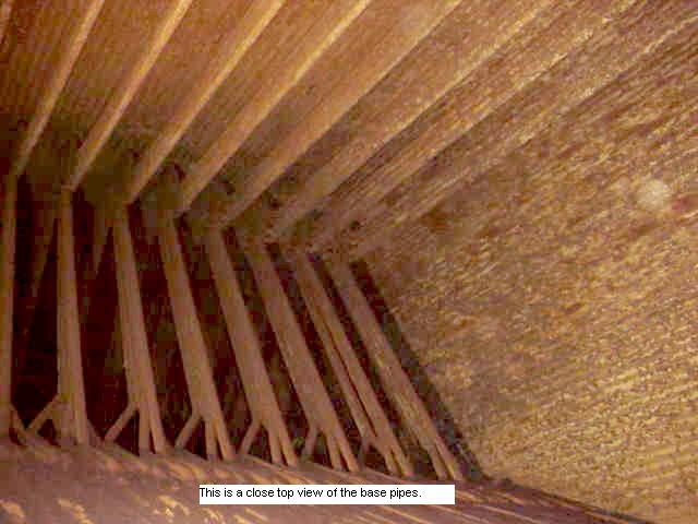
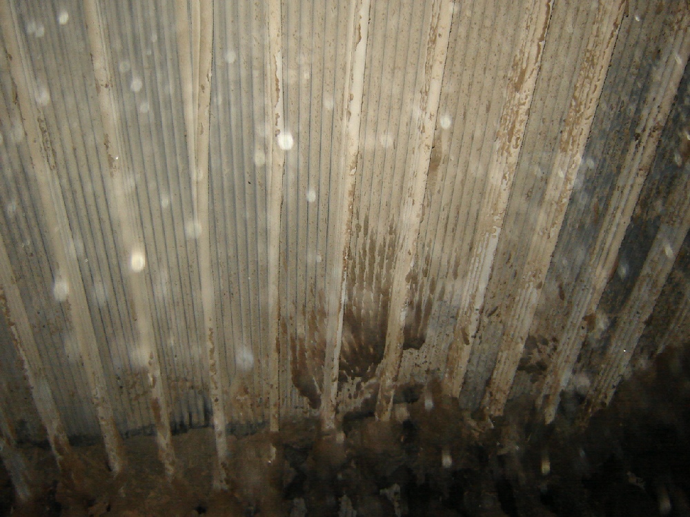
This is a view of the lower slope tubes that were used to support the Duct Balloon
The existing wall tubes are spaced 1’6” (457.2mm) apart and extend about 2’2” (660.4mm) away from the wall
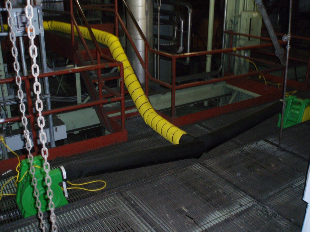
Here is how the 8” diameter (203mm) inflation tube was fed from blower to balloon
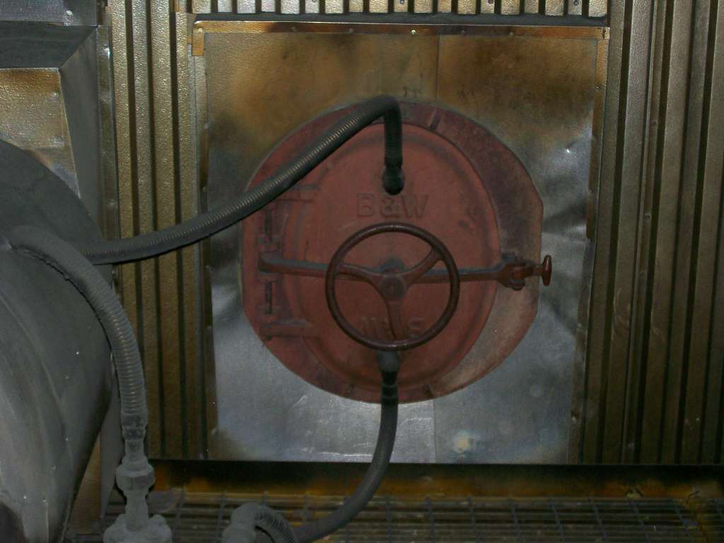
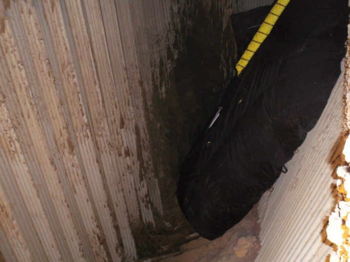
The is one of six existing access doors
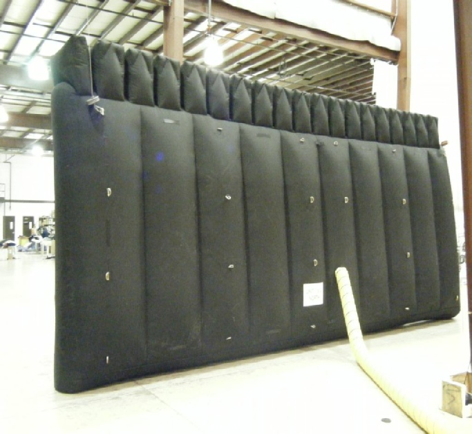
This is a view of the ½ size prototype Duct Balloon that was supplied to see how well it fit and to verify it’s ease of installation. Note how the “inflatable fingers” fit between the far side wall tubes to completely seal off the slope tubes above the work area and keep small debris from falling below.
This is a picture of one of two sections that were supplied on the project. Each section measured 28’ 7-
This is a view of one section that was lowered down into the boiler via the access door. Inflation time was less than two minutes for each section. Total installation time was about two hours for both sections. Each section deflates in five minutes by pulling the deflation zipper.


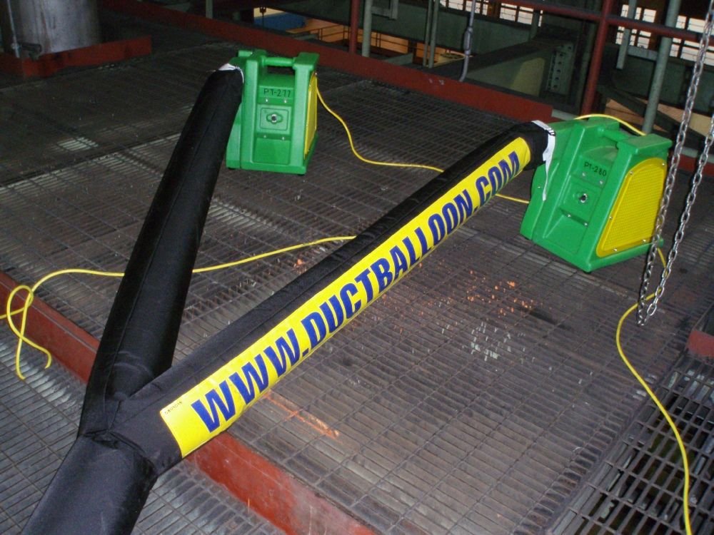
The flex duct inflation tube is connected between the Duct Balloon and the two 120V blowers.
While only one 120V is actually required, and additional blower is provided for redundancy.

| About Us |
| Articles |
| Technical Information |
| Testimonials |
| How it works |
| Weight Chart |
| Layout Drawing |
| Expansion Joint Areas |
| Tie Down Points |
| FGD's |
| FGD Outlet Duct Application |
| FGDs - Odor control during epoxy coating |
| Video Clip |
| Request for Quote |
| Installation Instructions |
| Repair Instructions |
| MSDS for Repair Adhesive |
| MSDS for Silicone Coated Fiberglass Fabric |