Duct Balloon®
Inflatable Isolation Barriers -

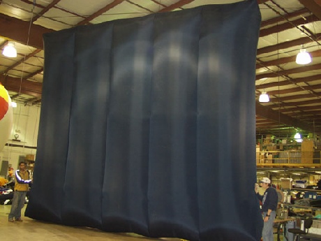

This is a 36’0” (10.9m) wide x 14’10” (4.52m) high x 3’0” (.9m) deep Duct Balloon that is installed in a FGD Absorber outlet duct. It weighs <100 lbs. (45 kg.) and can be installed in minutes. Due to the leaky isolation damper seals, it is used down stream (on the non-
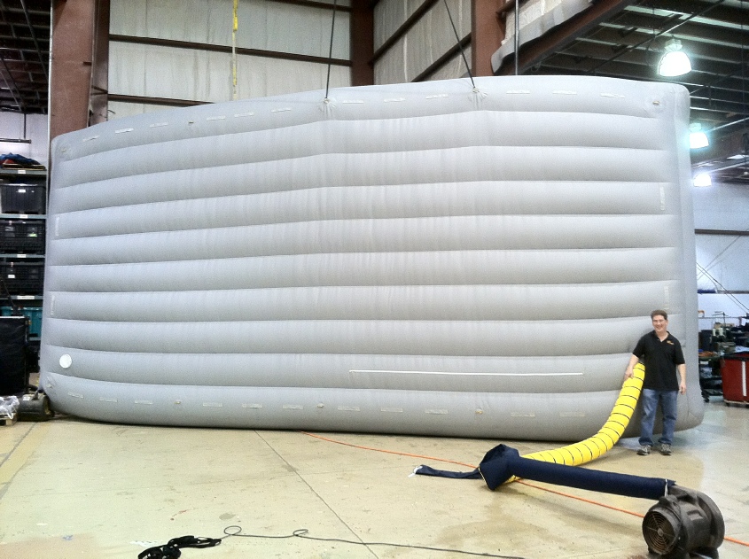
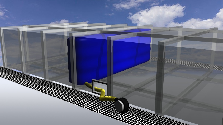
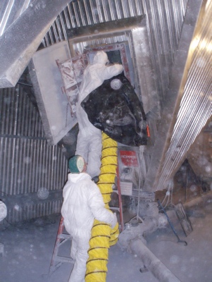
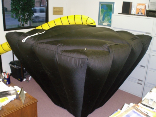
This is a 24’0” (7.3m) high x 20’0” (6.0m ) wide x 3’0” (.9m) deep Duct Balloon being tested before shipment. Even though it’s quite large, it will collapse down small enough so that it can pass through an existing 24” (609mm) x 30” (762mm) man way for quick installation and removal. It weighs about 95 lbs. (43 kg.) and can be inflated in less than five minutes. Deflation is accomplished by turning of the blower and opening the deflation zipper.


Due to plant cycling, weekend shut downs may occur many times during one year. If the plant will be down for a few days, a Stack Balloon can be inserted inside the exhaust stack after a 24 hour period to keep the residual heat “bottled up” inside the HRSG. Some plants use a combination of one Duct Balloon in the inlet duct in front of the IGV’s and one in the HRSG Exhaust Stack. The quantity and location on where to use them are based on the operating cycles of the plant, geographic location, corrosion prevention goals, outage requirements, etc. For more information, please click here.
*HRSGs that sit idle for extended periods of time are at risk of gas side corrosion from the humidity in ambient air. In North America, HRSG’s tend to sit idle more frequently in the fall and spring, which also coincide with wetter weather, increasing potential for damage unless preventative action is taken. Rain water and humidity entering through an open stack helps drive the corrosion process. Another driver is the change in ambient temperatures between day time and night time, where tube metal temperatures lag behind the daily high ambient temperature. When humid air contacts the cool tubes, condensation can occur, causing corrosion. This can be considered another form of “dew point corrosion”, except that entire sections of the HRSG’s typically are affected, not just a few rows of preheater tubes receiving cool feed water. *Excerpt taken from the HRSG Users Handbook distributed by the HRSG User's Group.
This is a 31’0” (9.44m) wide x 12’0” (3.65m) high x 3’0” (.9m) deep Duct Balloon that is made in Silicone Coated Fiberglass Fabric. This material is rated to 500ºF (260ºC) continuous and meets NFPA 701. The application is in a SCR Reactor on the man safe side of an existing damper to provide secondary isolation while in a bypass mode.
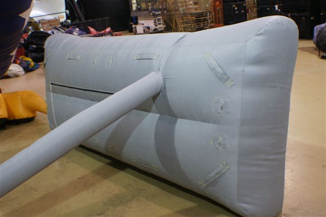
This one measures 9’7” (2.9m) x 3’6” (1.1m) x 2’6” (.76m) deep and is also made in Silicone Coated Fiberglass Fabric. The application is for ID Fan suction isolation where it will be installed in the inlet side of the ID fan, upstream of the inlet guide vanes.
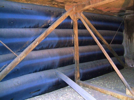
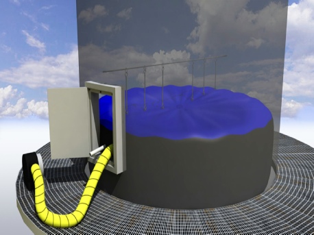
Many plants that have added scrubbers and baghouses have discovered that the isolation dampers do not seal properly during maintenance of forced draft or booster fans. While waiting for the next major outage is usually not an option, a method was developed to provide secondary isolation to an existing guillotine damper. This was accomplished by installing an access door below the damper, and then support pipes above and below the access door. A Duct Balloon is inserted inside the duct and inflated from outside the confined space. Note the open area above the access door which becomes the vent in a “double block and bleed” arrangement. This method creates additional isolation and allows work to be done in the confined space below the duct balloon while the unit remains on line.
They are custom designed inflatable barriers that can be inserted through most existing access doors and perform much better than wood frames and plastic sheeting. They are constructed out of a variety of durable wear resistant fabrics with some rated from -

This is a 28’6” (8.6m) wide x 8’6” (2.6m ) high x 3’0” (.9m) deep Duct Balloon installed in a SCR Outlet Duct. Installation was made in less than 30 minutes. Dual 120V/60hz blowers were provided to achieve redundancy. Being that the level of fly ash was very high, the blowers were located 80’0” (24.3m) away on grating outside the access door. Keeping fly ash from depositing on the SCR catalyst is necessary to avoid fouling at startup.
This is a 24’6” (7.4m) high x 12’6” (3.8m ) wide x 3’0” (.9m) deep Duct Balloon installed in the PJFF outlet duct. Installation was less than 20 minutes using two boilermakers and one supervisor. Deflation is quick by turning off the blowers and opening the deflation zippers. Either one of these Duct Balloons easily passes through the existing 2’6” (.76m) x 2’0” (.6m) access door.
During periods of layups or unit preservation, a Duct Balloon can be inserted in the duct between the filter banks and the inlet guide vanes to prevent the ingress of moisture laden air caused by the venturi effect of an idle engine.
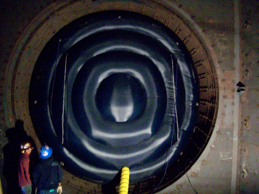
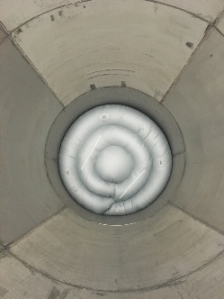
This 17’ (5.18m) diameter x 5’ (1.5m) deep Duct Balloon was installed between a Frame 7FA Gas Turbine and the HRSG at a 2 x 1 combined cycle plant in Texas. It functioned as a zero leakage barrier that isolated the space between the GT and the HRSG during CO2 blasting. This barrier was equipped with redundant blowers and reduced the outage window by allowing work to continue simultaneously on both areas of the plant. To learn more click here
A gas turbine OEM issued a technical advisory (TA) alerting plant owners and operators of a potential issue with GT disk embrittlement. To reduce the risk of disk embrittlement, turbine starts in cold weather are now temperature limited. This Duct Balloon measured 139” (3.53m) in diameter and the application was awarded a 2010 Best Practice Award by the Combined Cycle Journal.


Specially designed inflatable Duct Balloons can be used as temporary platforms in confined spaces. Company safety rules may dictate that any employee working in a confined space with inwardly converging walls must be able to exit the duct work without assistance, otherwise a confined space rescue team needs to be present. We offer specially designed Duct Balloons made to your duct work dimensions and shape that can be used as an inflatable platform versus scaffolding which can be labor intensive to install and result in increase outage times. Applications are in boilers, hoppers, pressure vessels, storage tanks, and many others.
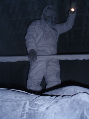
This inflatable platform is installed via the existing precipitator hopper access door and weighs less than 30 lbs. (13.6kg.) Installation is accomplished in minutes and it can support two men after it is fully inflated. For more information, please click here

This two minute real time video shows how easily a 10’ (3m) wide x 19’ (5.7m) high Duct Balloon can be set on the floor of duct work and be guided upwards until it reaches full inflation. All Duct Balloons are provided with one or two deflation zippers (depending on their size) which provide a quick method of deflating them so they can be quickly removed from the duct work.
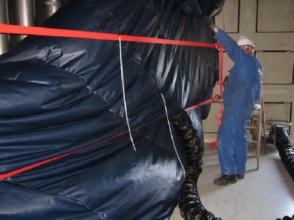
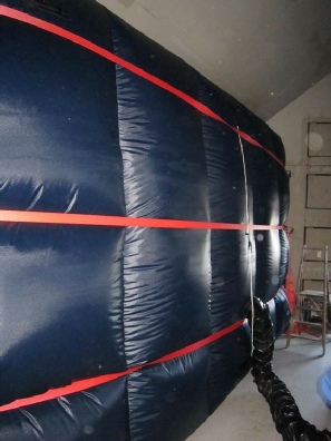
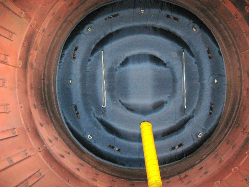
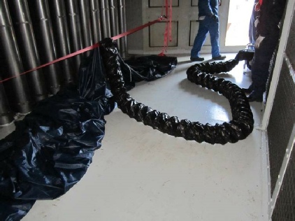
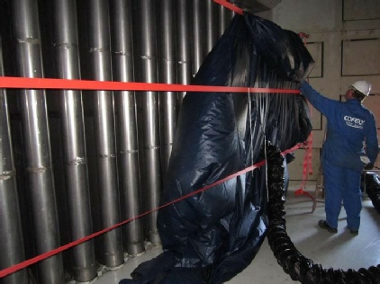
The CT Inlet Duct measured 18.07’ (5.51m) wide x 10.43’ (3.18m) high. The red nylon straps were used as additional restraints should the pressure differential be higher than the frictional forces created by the blower to keep it in place.
Installation time was less than 30 minutes. This CT Inlet Duct Balloon can be removed quickly by turning off the blower and opening the large deflation zippers which are attached to the white strings. Removal only takes minutes.
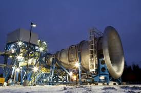
During periods of prolonged layup of a combustion turbine near a coastal region, a large Duct Balloon was installed in the CT inlet duct to stop the ingress of moisture laden air and sea salts. Being that this installation was at a refinery location, the supplied blower needed to be equipped with an intrinsically safe motor which meets Class 1 Div 1, Groups C and D and Class 2 Div. 1, and Groups E, F, G for US standards. Note that the special inflation tube was supplied in anti static spark resistant material in order to meet this standard.
Airworthiness regulations require manufacturers to demonstrate that aviation engines can tolerate a build-
| About Us |
| Articles |
| Technical Information |
| Testimonials |
| How it works |
| Weight Chart |
| Layout Drawing |
| Expansion Joint Areas |
| Tie Down Points |
| FGD's |
| FGD Outlet Duct Application |
| FGDs - Odor control during epoxy coating |
| Video Clip |
| Request for Quote |
| Installation Instructions |
| Repair Instructions |
| MSDS for Repair Adhesive |
| MSDS for Silicone Coated Fiberglass Fabric |