Duct Balloon®
Inflatable Isolation Barriers -


Every Duct Balloon is designed for a specific application based on the end users duct work size, space limitations, and installation environment. There are many items that dictate predictive holding capabilities which required physical testing and mathematical analysis.


Two methods shown below were used to secure the Duct Balloon in the test chamber. One method used steel chain secured to the duct wall and then to the anchor rings. Another method was to use steel chain between the anchor rings and anchored steel backing bars:
Secured with chain between the anchor rings and the duct
Secured with chain and steel bars inside the duct
Note: When using any type of tie down or support restraint system, it should always be designed by a professional engineer who is experienced in structural design. Failure to adhere to this rule could result in injury or death.


The chart below shows that different holding values can be achieved by using different perimeter thickness as well as different attachment methods inside the duct:
The test program showed that predictive holding values can vary between .5” w.g. (12.45mbar) by friction alone but as high as 10” w.g. (24.9mbar) if properly secured in the duct work. Generally speaking, the larger the size of the Duct Balloon the less pressure it will hold back before it starts to leak. For example, the predictive holding capability for a 10’ (3.04m) high x 10’ (3.04m) wide x 3’ (.09m) depth size using one 120V or 220V 2 HP high pressure blower is as follows:
Friction Method of Holding
Duct Pressure: .078 in H20 (.19mbar)
Force pushing on Duct Balloon: 407 pounds (184 kg.) at this pressure
Chain and Ring Method of Holding by securing inside duct to anchor rings
Duct Pressure : 4.80 in H20 (11.9mbar)
Force Pushing on Duct Balloon: 2497 pounds (1132 kg.) at this pressure
Horizontal Method of Holding by providing steel backing bar behind balloon
Duct Pressure 5.13 In H20 (13.2mbar)
Force pushing on Duct Balloon: 2668 pounds (1210 kg.) at this pressure
It must be understood that several variables can affect the accuracy of these predictive holding values such as Duct Balloon size, perimeter depth, material choice, duct surface conditions, method of restraining the Duct Balloon, atmospheric pressure, temperature, quantity of blowers used, as well as the over all integrity of the installation.
If you are considering installing a Duct Balloon in an area where it will see some pressure differential, you should be aware of a “double block and bleed” method which is shown in an artist rendering by clicking here. Always consult your company's safety department or the person in responsible charge before making a decision to use ANY type of temporary barrier!

The amount of pressure differential that a Duct Balloon can withstand before it moves or leaks is based on the method used to install it in the duct work. Using a test program designed by the Department of Aerospace Engineering at Penn State University, a thorough analysis was made by testing fabrics for coefficients of friction, as well as reviewing current product designs. Since their wind tunnel was a loop design and could not be used, a custom built pressure chamber was constructed that could be rated up to 20” w.g. (49.8mbar) Custom built Duct Balloons were supplied in various depths for the test chamber that could be connected to lab instrumentation to measure external and internal forces. Results developed from this testing are based on the following notes and equations:
The force required to cause an object to slide across any surface is called the frictional force (FF) and is defined as the coefficient of friction (μ) times the normal force (FN) between the two surfaces:
In the analysis of a Duct Balloon being held in a duct by friction, the frictional force (FF), must be equal to or greater than the pressure force (FD) being exerted on the frontal face of the balloon if it is expected to stay stationary:
… minimum requirement for a Duct Balloon to remain stationary
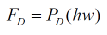
The pressure force (FD) is of course equal to the pressure (PD) multiplied by the surface area (hw) of the Duct Balloons frontal face:
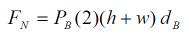
In contrast, the normal force (FN) must be equal to the balloon pressure (PB) multiplied by the duct surface area in contact with the Duct Balloons perimeter edge. This duct surface area is equal to the perimeter of the duct (2)(h+w), times the depth of the balloon (dB).
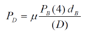
Combining the equations above, the minimum relationship needed between the duct pressure and the Duct Balloon pressure, for a stationary rectangular balloon, is presented below in Equation 1:
If this formula is changed to account for ducts of circular cross sections, with a diameter (D), it is presented below in Equation 2:
It is important to note that the ratio of the duct pressure / duct balloon pressure is therefore equal to (μ) times the ratio of the Duct Balloon surface area in contact with the duct / frontal face area.

FF = μ FN

| About Us |
| Articles |
| Technical Information |
| Testimonials |
| How it works |
| Weight Chart |
| Layout Drawing |
| Expansion Joint Areas |
| Tie Down Points |
| FGD's |
| FGD Outlet Duct Application |
| FGDs - Odor control during epoxy coating |
| Video Clip |
| Request for Quote |
| Installation Instructions |
| Repair Instructions |
| MSDS for Repair Adhesive |
| MSDS for Silicone Coated Fiberglass Fabric |